Briefing 03 / Pack control

Heat Where It Is Needed

A heating system succeeds when the relevant cells are ready for the intended duty—not simply when a heater has been switched on.

Cause / An energy and timing deficit

Define readiness before choosing hardware

The heating requirement starts with an operating question. Must the battery deliver a short power pulse, accept a planned charge or support a long discharge? Those tasks can have different temperature requirements. Establish the manufacturer-approved envelope for the actual cell and pack, then define the permitted waiting time and available energy source. A heater selected without this context may warm an enclosure efficiently yet fail to prepare the coldest cells in time.

Resistive films, pads or plates can transfer heat into a pack through nearby structures. Their effectiveness depends on contact, placement, electrical isolation and the path from the heated surface to the cells. A concentrated heater can create a local hot region while more distant cells remain cold. An installation therefore needs more than a nominal wattage: it needs an assessment of distribution, surface temperatures, sensor locations and behaviour if contact or airflow changes.

Compare complete heat paths

Liquid-based conditioning can distribute heat through channels or cold plates shared with a cooling system. It introduces pumps, valves, coolant properties and freeze-protection requirements. Air-based conditioning may be simpler in some enclosures but can struggle with uneven flow and heat transfer. Neither method is inherently best for all scales. The useful comparison includes the whole path from energy source to cell, together with maintenance needs, leak consequences and the intended environmental exposure.
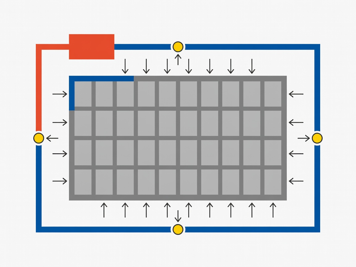
Flat vector diagram showing a heater, circulating fluid loop and temperature sensors distributing warmth around a battery module.
Conceptual heating paths. Actual layouts require pack-specific thermal and electrical validation.

Internal heating strategies using specially designed structures or controlled electrical excitation are also studied in research. They should not be interpreted as instructions to force current through a cold commercial pack. The electrochemical and electrical consequences depend on the method, cell design and control scheme. A laboratory demonstration of rapid warming is not evidence that an existing battery-management system can safely reproduce it. Modification requires a properly engineered and validated design.

Response / Measure, condition, permit

Make the control sequence explicit

A robust control sequence checks sensor plausibility, available supply, pack state and applicable limits before enabling heat. It monitors progress and stops or limits heating when conditions fall outside the validated envelope. Charging permission should depend on the relevant cell condition, not solely on elapsed heater time. The system must also handle sensor failure, a stuck switching device and loss of communication. These are design requirements, not details to add after a successful warm-up demonstration.

1 / AssessCheck temperatures, supply and sensor validity.
2 / ConditionWarm through a validated, monitored path.
3 / ConfirmEstablish readiness at relevant cell locations.
4 / OperateApply the correct charge or discharge limits.

Hysteresis can prevent rapid on-off switching around a control boundary, but its settings need a clear rationale. Sensor response time, mounting and thermal lag influence what the controller sees. A heater-side sensor may react long before the cell interior. During validation, compare those measurements with representative cell temperatures under several initial conditions. The goal is not an attractive average temperature; it is sufficient knowledge of the coldest and hottest relevant regions.

Put heating inside the energy budget

Electrical energy used by a heater is power integrated over time. Warming the battery also requires energy to raise its thermal mass, while heat continues escaping into the surroundings. Pumps, fans and controls add auxiliary demand. The useful result is therefore not just the extra discharge energy available after warming. Subtract conditioning energy and account for the waiting period, particularly when the battery itself supplies the heater during an outage.

Grid-connected preconditioning can preserve onboard energy for a vehicle’s journey or an installation’s reserve duty. It still consumes energy and may be unavailable after a supply failure. Scheduling heat close to departure or charge time can reduce the period over which losses must be replaced. Whether that strategy helps depends on forecast reliability, standby requirements and restart behaviour. A system that must be ready without warning needs a different plan from one with a dependable schedule.

Validation should include repeated cold starts, uneven initial temperatures, interrupted heating and a return to normal operation. Review the boundaries between heater controls, battery management and the charger or inverter. IEC 62619 addresses safety requirements for industrial secondary lithium cells and batteries; SAE J2929 concerns lithium-based propulsion battery system safety. Their relevance depends on the application and current edition. The next step is to carry this control logic into the complete winter installation.

Research starting points

NEXT: THE WINTER STORAGE CYCLE